河北翔悅工程咨詢有限公司成立于2007年,辦公地址位于河北省廊坊市廣陽區(qū)格林郡府商務(wù)中心,注冊資本三百余萬元,是一家具有獨(dú)立法人資格的專業(yè)工程咨詢公司。近年來,我公司業(yè)務(wù)發(fā)展迅速,目前已涉足建筑、機(jī)電、市政、公路、水利、農(nóng)業(yè)、信息化、醫(yī)藥等行業(yè),涵蓋項(xiàng)目前期咨詢、項(xiàng)目規(guī)劃、工程設(shè)計(jì)、工程造價咨詢、項(xiàng)目全過程管理、造價糾紛鑒定、政府投資評價、財政績效評價等多個業(yè)務(wù)領(lǐng)域,成為京冿冀區(qū)域較有影響力的專業(yè)咨詢機(jī)構(gòu)。 河北翔悅工程咨詢有限公司具有工程造價咨詢甲級資質(zhì),通過了ISO9001國際質(zhì)量體系認(rèn)證、ISO14001環(huán)境管理體系、ISO45001職業(yè)健康安全管理體系認(rèn)證,2020年獲得··· |
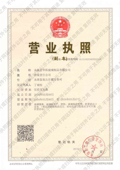


執(zhí)照")
證書")


 冀公網(wǎng)安備 13100302000916號
 ??客戶咨詢